
Rod Ends - Overview, Mounting, and Fitting
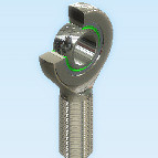
Rod ends consist of an eye-shaped head with integral shank forming a housing and a standard spherical plain bearing, or a spherical plain bearing inner ring, or a spherical plain bearing inner ring and a sliding layer between the bore of the head and the inner ring. As a rule, rod ends are available with left or right-hand female or male threads. Most manufacturers also provide rod ends in both inch and metric dimensions. Rod ends have the sliding contact surface combinations steel-on-steel, steel-on-bronze, steel-on-PTFE composite material, steel-on-PTFE fabric and steel-on-PTFE plastic.
Steel-on-steel and steel-on-bronze rod ends have very wear-resistant sliding surfaces and perform well under conditions of lubricant starvation. Rod ends with this sliding contact surface combination require regular relubrication. They are particularly suited for bearing arrangements where heavy alternating loads have to be accommodated.
Maintenance-free rod ends sliding contact surfaces have three groups: steel-on-PTFE composite material, steel-on-PTFE fabric and steel-on-PTFE plastic. They have very low friction and can be operated without maintenance. They are used for applications where long bearing lives are required without maintenance, or where operating conditions, such as inadequate lubrication or the absence of lubrication make the use of steel-on-steel bearing inadvisable. The maintenance-free bearings are primarily intended for applications where loads are heavy and have a constant direction.
Mounting Rod Ends
To facilitate mounting, the ends of pins or shafts and the edges of housing bores should have a lead chamfer of 10° to 20°. The bearings can be more easily pressed into position and there is little risk of damage to the mating surfaces being caused by skewing of the bearing.
When mounting spherical plain bearings with a fractured or two-part outer ring, it is essential that the joint should be positioned at 90? to the main load direction; otherwise the service life will be shortened, particularly under heavy loads. Also, the bearing’s lubrication holes will be placed in the load zone, allowing lubricant distribution where it is needed most.
Bearing rings should NEVER be hammered into place. Only apply mounting forces onto the ring that is being mounted (i.e. force on outer ring if being pressed into a housing, force on inner ring if pressed onto a shaft). NEVER apply mounting forces though the bearing’s sliding surfaces, this will damage the bearing and will severely decrease its service life. In the event that the bearing has a press fit on both the inner and outer rings, a special tool should be made to allow pressing of both components simultaneously.
Other ways of mounting rod ends with the facilitation of heat or refrigeration, or with the use of adhesives may be possible also, please contact AST Engineering for further assistance.
Fitting Rod Ends
Generally, outer rings of Spherical Plain bearings get press fit into housings. This allows the fracture to remain closed, and prevents rotation of the outer ring under heavy rotational or oscillating loads. Inner rings may have interference or clearance fits on shafts depending on the application. Below is a list of suggested fits for various conditions. Please contact AST Engineering for any further assistance needed.
Fits For Rod End Bearings
The following charts show the various fits for rod end bearings including: shaft and thread fits along with shaft diameter tolerances.
Shaft Fits for Rod Ends
|
Operating Conditions
|
Tolerance
|
|
With Intermediate Loads
|
n6, p6
|
|
Normal Conditions
|
h6, h7
|
Thread Fits for Rod Ends
|
Male Threads
|
Female Threads
|
|
6g
|
6H
|
|
UNF-2A
|
UNF-2B
|
Shaft Diameter Tolerances for Rod Ends
|
|
Shaft Diameter Tolerances (µm)
|
||||||||
|
Shaft Diameter (mm)
|
h6
|
h7
|
n6
|
p6
|
|||||
|
Over
|
Incl.
|
High
|
Low
|
High
|
Low
|
High
|
Low
|
High
|
Low
|
|
3
|
6
|
0
|
-8
|
0
|
-12
|
+16
|
+8
|
+20
|
+12
|
|
6
|
10
|
0
|
-9
|
0
|
-15
|
+19
|
+10
|
+24
|
+15
|
|
10
|
18
|
0
|
-11
|
0
|
-18
|
+23
|
+12
|
+29
|
+18
|
|
18
|
30
|
0
|
-13
|
0
|
-21
|
+28
|
+15
|
+35
|
+22
|
|
30
|
50
|
0
|
-16
|
0
|
-25
|
+33
|
+17
|
+42
|
+26
|
|
50
|
80
|
0
|
-19
|
0
|
-30
|
+39
|
+20
|
+51
|
+32
|
|
80
|
120
|
0
|
-22
|
0
|
-35
|
+45
|
+23
|
+59
|
+37
|
|
120
|
180
|
0
|
-25
|
0
|
-40
|
+52
|
+27
|
+68
|
+43
|
|
180
|
200
|
0
|
-29
|
0
|
-46
|
+60
|
+31
|
+79
|
+50
|