Needle Roller Bearings - General Overview
Nomenclature
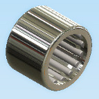
 The prefix letter or letters in the needle roller bearing designation for Drawn Cup (DC) bearings denote whether the bearings are made to inch or metric nominal dimensions as well as their major construction features. For example, a bearing with metric nominal dimensions is indicated by the code letter HK having open ends and letters BK for closed ends, in the prefix. Letters in the prefix other than HK, or BK indicate a bearing of inch nominal dimensions. Most sizes of inch bearings are available with either a full complement of rollers or caged rollers. Metric bearings are available with caged rollers as a standard. The use of caged rollers in inch bearings is indicated by the prefix code letters SCE. In addition to these major features of dimension and construction, there can be other identifying letters which cover special modifications.
Full Complement Bearing Construction
The full complement drawn cup needle roller bearing employs a full complement of rollers. The full complement drawn cup bearing combines maximum capacity and low cost with the advantages of the drawn outer ring.
The inward turned lips of the cup are used to mechanically retain the full complement of needle rollers to provide positive radial retention of the rollers even though it may be necessary to remove the shaft repeatedly during the servicing of the mechanism with the bearing.
Caged Bearing Construction
Caged drawn cup bearings have a steel cage which provides inward retention of the needle rollers. The design provides maximum cage strength consistent with the long life requirements. Bearings are also available with reinforced plastic cages, for use where operating conditions permit. Before applying bearings with plastic cages please contact AST sales or engineering personnel.
Sealed Bearings
Caged drawn cup caged needle roller bearings are offered with integral seals on certain sizes. The lip contact seals limit the bearing operating temperature between -25° F and +225° F (-30° C and +110° C). The seal lip design achieves a light and constant contact with the shaft throughout the range of mounting bearing clearances thereby ensuring positive sealing and low frictional drag. Sealed drawn cup bearings are intended to retain grease or non-pressurized oil within a bearing while also preventing contaminants entering the raceway area. The standard lip contact seals are compatible with common lubricating oils and petroleum based fuels, but they are adversely affected by certain fire-resistant hydraulic fluids and most common solvents.
Mounting and Fits
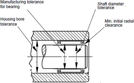
Drawn cup bearings are manufactured to meet the radial clearance requirements of most applications. The total radial clearance of an installed DC bearing results from the build-up of manufacturing tolerances of the housing bore, inner raceway O.D. and the bearing, as well as the minimum radial clearance required for the application. The recommended mounting dimensions will provide correct running clearance for most applications. Closer control of radial clearance is governed by the user’s capability of holding housing and shaft raceway dimensional tolerances tighter. The drawing illustrates an example of the manufacturing tolerances and the built-in clearances applying to medium size drawn cup bearings in rotating applications. Radial clearance in a mounted bearing may be more closely controlled by reducing the manufacturing tolerances of the housing bore and inner raceway diameter.

Installation Procedures
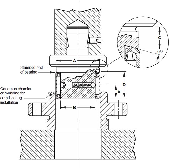
A drawn cup bearing must be pressed into its housing. An installation tool similar to the one illustrated must be used in conjunction with a standard press. It is advisable to utilize a positive stop on the press tool to locate the bearing properly in the housing. The assembly tool should have a leader or pilot, as shown, to aid in starting the bearing true in the housing. The installation tool must be coaxial with the housing bore. The ball detent shown on the drawing is used to assist in aligning the rollers of a full complement bearing during installation and to hold the bearing on the installation tool. Assemble the bearing with the stamped end (the end with identification markings) against the angled shoulder of the pressing tool. Never hammer the bearing into its housing even in conjunction with the proper assembly mandrel. Never press the bearing tightly against a shoulder in the housing. If it is necessary to use a shouldered housing, the depth of the housing bore must be sufficient to ensure the housing shoulder fillet, as well as the shoulder face, clears the bearing. To remove a drawn cup bearing from a through-bored housing, use a tool similar to the installation tool illustrated, but without the stop.

Inspection Procedures
Although the bearing cup (outer ring) is accurately drawn from strip steel it may go out of round during heat treatment. When the bearing is pressed into a true round housing or ring gauge of correct size and wall thickness, it becomes round and is sized properly. For this reason, it is incorrect to inspect an unmounted drawn cup bearing by measuring the O.D. The correct method for inspecting the bearing size is to:
- Press the bearing into a ring gauge of proper size.
- Plug the bearing bore with the appropriate “go” and “no go” gauges.
The dimensions of the correct ring and plug gauge diameters for inspecting drawn cup needle roller bearings are available from the AST Bearings technical department upon request.

